Bicycle and lift
Bicycle carriage – lift.
 Often, the location of the apiary does not allow it to approach it on a truck fairly close, and it is not easy to transport multi-hull beams for a relatively large distance by a hand cart. It is much faster and easier to do this with the help of a bicycle-lift truck.
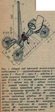
The frame 12 of such a trolley is welded from pipe sections with a diameter of 34 mm.
The rear axle 9 is made from a rod on which the seats for the drive sprocket from the bicycle and the bearings are protruded. The asterisk is fixed on the middle of the axis; bearings are closer to the edges with bushings 8, and at the ends of the axis are fixed bicycle wheels 10. The assembled axle is attached to the frame by means of pins welded to the bushings 8 and fixed with pins.
The bushings 23 are vertically welded to the forward ends of the frame tubes and rotary brackets 24 with semi-axes 21 are pivotally attached to them by means of bolts-axles 21 on which the front wheels 22 covered by shields 27 are welded. A transverse pipe with a lifting boom 1 is welded to the front part of the frame, consisting of two parallel non-contiguous pipes with a diameter of 27 mm. At the top of the pipe, booms 1 are bolted 3, which serves as the axis of roller 2. A movable coupling 29 with load-holding forks 28 is mounted on the boom. A self-locking winch 5 with a chain sprocket from a bicycle mounted on the axis of the handle of the winch is fixed to brackets 18. The cable 4 from the winch is thrown over the roller 2 and hooked onto the bolt 30 on the vertical pipe of the forklifts.

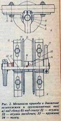
The mechanism for driving the truck and the load forks is attached to the tubes of the frame by brackets 14. It consists of an axis 16 with pedals 17 and two chain sprockets 15 welded to the sleeves 32. The axle is spring-loaded with respect to the guide sleeves
Washers were used to reduce friction along the end surfaces. The spring will work better if you make a longitudinal groove on the axis, and put a washer with an inner tine between the spring and the bush,
The left sprocket is connected by a chain drive with a drive sprocket on the rear axle 9, and the right sprocket with an asterisk on the winch 5. The gears are rotated from the pedals to the sprockets by pressing the axle 16 with a finger 34 entering special grooves on the sprockets 32 of the sprockets. The spring constantly presses the axis 16 to the left, so when you turn the pedals the finger enters the notch on the bush of the left sprocket. Thus, the work of the mechanism is automatically supported in the drive mode of moving the bicycle.
To put the drive in the lift mode, it is enough to press the axis to the right, to turn the pedals in the direction in which they will be rotated. In this case, the finger 34 is pressed against the end of the bushing of the right sprocket and enters the shaped groove as soon as it is opposite to it.
When the pedals are depressed, the spring is released: the finger is fixed in the new position. To change the direction of rotation of the right sprocket, press the left pedal to the right when turning to reverse rotation. Otherwise, when reversing the direction of rotation of the pedals, the mechanism automatically switches to the drive mode for moving the bicycle.
The steering pipe 6 is passed through the sleeve 7 and fixed in the axial direction with respect to it by pins with washers; the second point of support is the cylindrical end of the coil 19, inserted into the hole on the boom 1, inserted into the pipe 6. The rope is wound on the spool, the ends of which are connected to the steering arm 20 passed in the brackets under the transverse pipe of the frame. With the longitudinal ends of the rod, the arms 26 welded to the pivot brackets 24 are hingedly connected.
The chains are tensioned by means of longitudinal grooves in brackets 18 and 14. The drive chain is closed by a casing 13 attached to the winch bracket and the stand under the seat. The bicycle carriage is equipped with a hand brake 11.
To transport the hive, a cart is brought to him, the pedal axis is pressed with the left foot and the drive is put into the lift mode. Rotating the pedals, unwind the cable from the winch drum: the gripping forks under their own weight fall below the bottom of the hive, after which they turn the pedals in the opposite direction – the drive automatically switches and drives the sprocket of the rear axle.
The bicycle carrier rolls forward until the load forks are placed under the bottom of the hive – the wheels go along the front and back walls of the hive. Then turn on the right star of the drive mechanism and, rotating the pedals, raise the hive to a comfortable height. Switch the drive again and transport the hive to another place or to load.
When inspecting families occupying several hulls of a multi-hull, the bicycle elevator truck is additionally equipped with a gripper, whose L-shaped rods are inserted into the tubes of the load-holding forks with eccentric handles and adjusting nuts.
Having seized the hive, without descending from the trolley, turn the bent ends of the gripping rods into a horizontal position, eccentric handles clamp the necessary body and, lifting it over the lower, move back. After inspection, the upper shell is returned to its place.
Velotelezhka-lift allows you to change the shell in places, move, load and unload not only beehives, but other cargo.
Collapsible forklift hives. In apiaries where there are no lift trucks or serial loading devices, it is possible to load the hives into a motor vehicle using simple lifts.

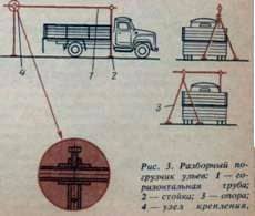
Such a lift consists of a horizontal pipe 1 with a diameter of at least 34 mm (the diameter of the pipe depends on the length of the platform of the vehicle), column 2 and support 3 of pipes with a diameter of 34 mm. The horizontal pipe is supported on one end by a pillar hammered into the ground and secured by the bracket to the front of the car, and the second by a two-legged support, spaced from the tailgate to a distance sufficient for the carriage with the hive. The nodes 4 of the horizontal pipe fastening to the post and support are made in the form of a ring to which a metal rod is welded on one side and a boss with a thread for the locking screw, on the other.
Collecting the lift, first install and fasten the post 2, from above the rod is put into the pipe inside the pipe. A horizontal tube is introduced into the ring of the assembly, a roller and a second attachment unit are put on it. Install a two-legged support, a metal rod with a ring is fed into the support pipe. Locking screws fix horizontal pipe. A pulley or a winch with a grip is suspended to the pulley.

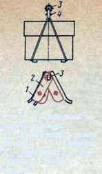
Fig. 4. Grapple gripper for hives: a) construction of the lock grip: 1 – hooks; 2 – plates; 3 – suspension bracket; 4 – the pin.
For the loading of the hive-loungers, a clamshell gripper is convenient, consisting of four tubular hooks 1 to which are welded three metal plates 2 forming a lock. Two holes are drilled in the plates: the upper ones are used to secure the suspension bracket or ring 3, the lower ones are used to fix the hive in the gripper with the help of pin 4, which prevents opening of the hooks. The gripper is simple in design and is made of a tube with a diameter of 22-27 mm and a strip 5 mm thick.
Bicycle and lift

