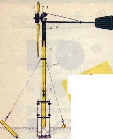
Fig. 1. Two-bladed wind power unit:
1 – windmill; 2 – reducer; 3 – generator; 4 – support; 5 – tail; 6 – post; 7 – extensions; 8 – the lever.
Correctly made windy unit at good service works 5-7 years without special expenses. It generates electric energy sufficient to illuminate two or three small rooms, power radio receivers, charge batteries, it is used to raise water from a depth of up to 15 m, driving millstones, etc.
The main element of the wind power or wind power plant is the windmill ¶. Low-power units that run on the generator, usually mounted on a pole or pipe with stretches. When making a wind power unit, it is necessary to select the correct generator (decommissioned autotractor), a rectifier and a current regulator, to determine the dimensions of the windmill, to make its blades qualitatively, to choose a speed controller. For better use of wind energy, it is convenient for the wind power unit to drive not only a water pump, but also a generator for lighting and charging batteries.
When choosing lamps for lighting, it is necessary to take into account that low-voltage lighting lamps of automotive type have a good light output. So, one bulb with a power of 15-20 W is enough to illuminate a room of 6-8 m2.
When choosing the required capacity of the wind power unit, one must take into account the strength of the wind. In particular, in Ukraine, the average annual wind speed does not exceed 5 m / s. The power and speed of the windmill should be calculated for the wind speed at which the wind turbine generates maximum power throughout the year. In areas with an average annual wind speed of 3-5 m / s, it is equal to 8 m / s. At this speed it is customary to calculate the power and the maximum speed of rotation of the windmill. This means that the power and frequency of rotation of the wind turbine at a wind speed exceeding 8 m / s should be practically constant.
The simplest wind power unit is shown in Fig. 2, its wiring diagram is shown in Fig. 3.
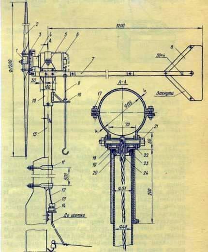
Fig. 2. Wind power unit with a generator; 1 – the overlay; 2 – windmill; 3 – a brake pulley; 4 – the generator of a direct current; 5 – a clamp with four groves; 6 – a casing; 7 – Tail of the tail; 8 – feather tail; 9 – draft of a brake; 10-bracket; 11-yoke; 12 – flexible wire; 13 – plug; 14 – the socket outlet; 15 – support tube; 16 – head support; 17 – a bolt; 18 – spacer bushing; 19 – ring; 20 – the bushing; 21 – a bolt; 22 – the brake lever; 23 – thrust bushing; 24 – rubber tube.
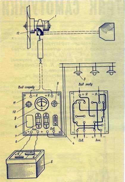
Fig. 3. Wiring diagram of the electrical equipment of the wind power unit:
1 – generator; 2 – the start button; 3 – the lamp; 4 – the switch; 5 – the battery; 6 – clamp; 7 – fuse; 8 – reverse current relay; 9 – ammeter; 10 – signal lamp; 11 – textolite panel; 12 – the screw of weight.
To strengthen the hub of the windmill and prevent its crushing, it has a fixed lining in front of it, and behind it there is a brake pulley, bolted to the blade with two bolts. The windmill is mounted on the generator shaft and fixed with a nut and a washer. The generator is fixed to the support by a yoke. The support is made of a two-inch pipe 200 mm long, to which a 100 × 4 mm steel strip seat has been welded. The generator’s support is clad in a tube on which it rotates freely. Thanks to this, the unit can be installed on the wind with the help of a tail, which consists of a bar and feathering. At the end of the support tube is a gasket made of brass with a thickness of 1-1.5 mm, on which the support spins. This gasket together with a ring, a bush and a pipe forms a bearing bearing.
The unit is stopped by means of a brake, which consists of a brake pulley and a staple curved over the outer radius of the pulley and riveted to the lever that surrounds the generator support. In the lever jumper there are two holes into which the return spring and the hook of the pull of the manual stop system pass. To stop the windmill, pull it downwards.
The support tube is attached to the pole of the mast with two clamps.
The current from the generator is fed into the shield by a flexible cable or wire.
Specification of parts of the wind power unit
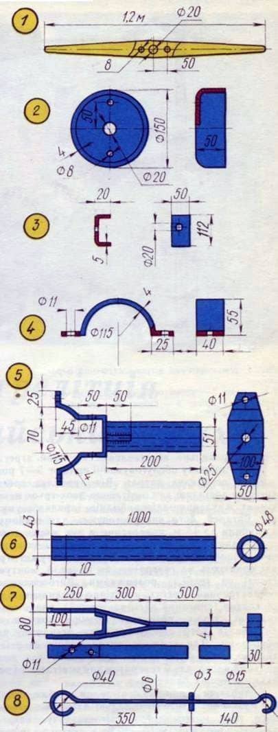
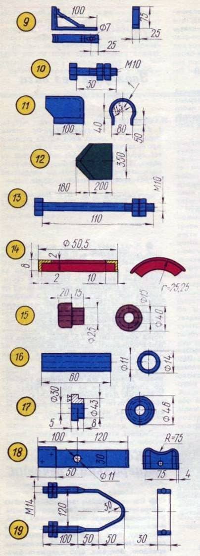
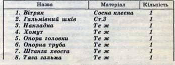
Propeller; 2. Brake pulley; 3. The tab; 4. Khemut; 5. Head support; 6. Support pipe; 7. Tail of the tail; 8. Brake draft;
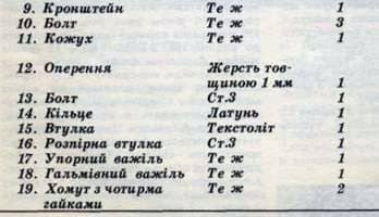
9. Bracket; 10. Bolt; 11. Casing; 12. Plumage; 13. Bolt; 14. The ring; 15. Bushing;
16. Spacer sleeve; 17. The persistent pedal; 18. Brake pedal; 19. A yoke with four nuts.
Generator selection
Generators of low-power wind turbines operate at a changeable rotational speed, i. e. in the same conditions as generators of cars, tractors, combines, buses. These generators, almost without changing the electrical circuits and structures, are used for homemade wind power units.
The power required to drive the generator at the rated speed is determined by the formula:
P = (1.7-2). Rg. n.
Where: – rated or calculated generator power; the coefficient of 1.7-2 is a constant value.
For example, we have an alternating current generator G-253 with a capacity of 0.475 kW. To determine the power required to drive this generator, substitute the data in the formula:
P = (1.7-2) 0.475. P = 950 W.
The wind turbine can only function stably when the power of the windmill is 20-30% higher than the power required to drive the generator. Hence the diameter of the windmill windmill
D = / 5-5.7 / x vRg. g., m,
Where the coefficient 5-5,7 is a constant value. So, for a given generator, the diameter of the windmill should be: D = (5-5.7) x v0.475, m = 5 x 0.22 ~ 1.1 m.
The speed of rotation of the windmill with the maximum coefficient of wind energy use is as follows:
N = 60 x ZnV: nD
Accept the wind speed V = 8 m / s, the speed of Zn = 7. Then
N = 1070: D rpm.
Hence the maximum speed of circulation of our windmill should not exceed:
N = 1070: 1.1 = 972 rpm
Selecting a location for the wind farm
The speed of the wind flow is significantly affected by various obstacles, the terrain. It must be borne in mind that not every hill is suitable for installing a wind farm. Thus, at the top of a hill with steep slopes due to the swirling of air, the windmill will not be completely in the area of the wind flow and its rotation frequency will be lower than below in the plain. Through this, for the installation of the wind turbine, it is necessary to choose even places or elevated ones with gentle slopes.
It is not recommended to install the unit near ravines, with steep slopes, as the airflow, passing across, disrupts the operation of the windmill.
The site for the unit must be open from all sides and raised above the surrounding terrain. If there is no such place, it is necessary to install the unit in the direction of the wind (“wind roses”).
These data can be obtained at the nearest meteorological station.
Safety precautions
Vetroagregaty must be strong and safe. The minimum height of the tower for the windmill should be such that the lower end of the windmill is 1.5-2 m above the nearest obstacle. Change the size of the details of the wind farm, which are listed in the article, you can only in the direction of increasing them. Units with a windmill with a diameter greater than 1.5 m are permitted to be operated only if there is a mechanism that prevents an increase in the speed of rotation of the windmill and the power it develops.
Windmill in-house
Almost the most important of the components of the windmill is the blades. That is why we will elaborate on their manufacture in detail. The power of the wind turbine depends on the shape and quality of the blades. For low-power – use a two-bladed windmill. The blades in it are screw-shaped. At the same time, an advantageous angle of attack (the angle at which the wind runs over each element of the blade) is formed and the angle of the wedge (the angle formed by the blade with the plane of rotation of the windmill) is changed along the entire length of the blade.
Winding blades of the windmill are made using templates, the parameters of which are calculated. For calculations, take the diameter of the windmill A = 1 m, speed – 7 (the ratio of the circular speed of the blade end to wind speed) and the coefficient of wind energy use K = 0.35.
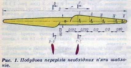
Fig.1 Construction of sections of the necessary five templates.
The cuts of the patterns for making the blades of the windmill are shown in Fig. 1, and the coordinates for the construction of templates of blades with a diameter of 1 m – in Table. 1 and 2 (the location of the coordinate is shown in Figure 2).
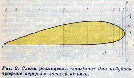
Fig. 2 Scheme of location of coordinates for constructing profile sections of blades.
1. The dimensions of the blades
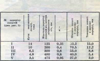
1. The sections of the blades, see Fig. 1
2. Blade wedge angles
3. Distance of the incisions of the blades from the center of the wind wheel
4. The width of the blade in this section
5. The thickness of the blade in this section
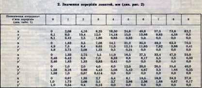
2. The values of the cuts of blades, mm see Fig. 2
If it is necessary to construct a blade profile for a windmill with a diameter greater than or less than 1 m, all dimensions of tables 1 and 2 need to be changed by multiplying them by the diameter of the windmill that they produce (in meters). Only the angles of the wedging in each blade cut will remain unchanged, as well as the number of cuts. For example, for a windmill with a diameter of 1.2 m, each size of tables 1 and 2 should be multiplied by 1.2.
To obtain the finished shape of the blade, it is necessary, for the appropriate dimensions, to build on the sheet of paper the points for the five profiles of the blade and to trace the contours along the points by means of a curve.
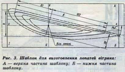
Fig. 3 Template for making blades
A-top of the template
B-lower part of the template
An example of a template for the first section (see Figure 1) is shown in Fig. 3. In this case, the following designation is accepted: a dash-dot line – the template contour for A = 1.2 m; a dash-dotted line with two points – for A = 1.5 m; Solid – for A = 2 m; dashed – the outline of the template for A = 2.5 m.
The profiles of each cut are drawn in full size in order to cut out the templates when manufacturing blades.
Wooden blade
Made from well-dried pine, ash, maple or lime boards, which should not have defects (knots, curvatures, rotten, etc.). On one windmill you need four boards 4-5 cm longer than the blade’s length.
Use casein glue, carpentry is not suitable, because it is not moisture resistant. Adhesive with an equal layer and rapid movements are applied with a brush to the boards, which are laid one on one and clamped with clamps or twisted by a wire with an interval of about 300 mm. In order not to damage the surface of the boards, thin plates are placed in the places of tightening. The glued boards are dried for two days in a dry room at room temperature. In summer they can be dried under a canopy.
Then the side surfaces of the prepared boards are treated with a jointer. The preform is pre-fitted under a template made of thick paper or paperboard and adhered to its surface. The approximate dimensions of the blade blanks are given in Table. 3 (see Figures 1 and 3).
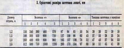
Fig.3 Approximate dimensions of blades blanks, mm
On the cut blank, blades in its center are drilled with a hole 16-18 mm in diameter. Processing glued boards on templates on a control board with a width of at least 250 mm when making blades with a diameter of 2.5 m and on a board of smaller width – for a smaller diameter of a windmill. In the central hole of the board, fix the pin 16-18 mm in diameter with two nuts.
Along the board, an axial line is applied, and grooves 8-10 mm in depth and width are made across it, which corresponds to the thickness of the patterns that will be inserted into the slits.
Templates are made of plywood 4-6 mm thick, cut into rectangles measuring 250 X 80 mm, on which the wasps XX and Y – Y are applied, strictly perpendicular to one to one and parallel to the sides of the rectangles.
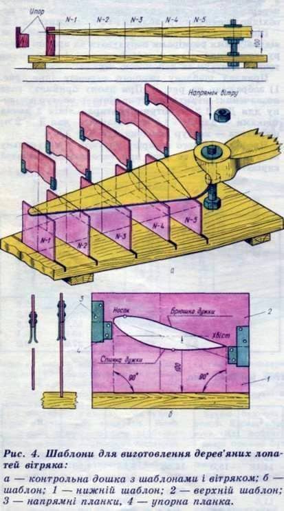
Fig.4 Template for the manufacture of wooden blades
A-control board with template and windmill
B-template
1-lower template
2-Upper Template
3-way rail
4-way bar
The XX axis should be slightly offset and should be 100 mm from one of the edges of the rectangle. The cross section of the axes forms the center of the section profile of the blade.
Using Fig. 4, apply and cut out the profile contours. Then the patterns are cut into two parts, as shown in the figure. When compiling the two halves, the contour of the cutout must exactly match the profile.
Using templates that are installed in the slots of the control board, further processing of the workpiece is carried out. The lower halves of the patterns are set in the cutouts of the board so that the X-X axis of the patterns is exactly at one height from the board, and the Y-Y axis coincides with the blade axis on the control board.
The edges of the lower part of the patterns are smeared with paint and the blade blank is lowered on them, putting it on the pin in the control board and combining the workpiece axis with the axis of the board.
In the places of touching the workpiece with the patterns there will be a trace of paint. The workpiece is removed from the hairpin and in the places of marking the paint is cut with a chisel of a groove 8-10 mm wide and 3-5 mm deep. The template is again smeared with paint and put on the blade.
At the marking points, the pits are made 2-3 mm deep. Such operations are continued until the cuts on the workpiece coincide with the profiles of the lower template. Then they remove the workpiece, twist two nuts on the pin, re-insert the workpiece and, placing it on the previous place (template), bring the nuts under the lower part of the hub of the future blade. This nut is locked by the other and does not untwist it until the end of the blade manufacturing. The workpiece is lifted on the hairpin (without removing it from it), it is rotated around the axis of the stud by 180 њ and the half of the blade is treated in the same way to the friend until the planes of all the cuts are completely adhered to the bottom of the patterns.
The upper surfaces of the blades are processed along the upper halves of the templates in the same way as the lower part. After this, five belts are formed on both blades, the profile of which corresponds to the profile of the blade. Unprocessed part of the workpiece is carefully removed with a plane to the line of paint on the belts. The surface of the blade is finally ground with sandpaper, cover with two layers of nitro primer, unevenness is cleaned. The spade is colored with nitrocellulose (twice) and can be covered with 3-4 layers of BF-2 glue with the next drying of each layer.
A ready-made windmill must be balanced.
Manufacturing of a metal blade
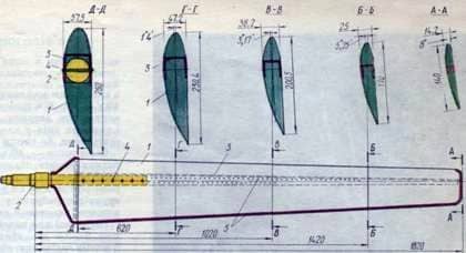
Fig. 5. The metal blade of the windmill:
1 – cladding; 2 – shaft; 3 spar; 4 – large rivet; 5 – small rivet.
It consists of a skin 1 with a thickness of 0.5-0.7 mm, a box spar 3 (sheet steel 1.5-2 mm thick) and a shaft 2.
To provide the necessary profile of the blade, a blank and slug are prepared. Bolvanka is a copy of the blade made of solid wood (beech, oak, pine in extreme cases). The upper half of the blade skin is formed on the disc.
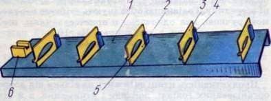
Fig. 6. Staple:
1- Channel channel; 2- lower template; C – upper template; 4- the hinge axis; 5 coupling bolt; 6- boss for the shaft.
Stapel is the channel 1, to which the templates are welded. Lower 2 and upper 3 templates are connected with a bolt, passed through the loop.
The lining of the blade, pre-curved on the disc, is laid in a slipway, compressed by templates and its edges are joined by rivets 3-4 mm in diameter. After that, the plating is removed from the slipway, the edges are cut off, the edges are sealed and the blade is painted inside, pouring into it a nitro primer.
Then the lining is reinstalled into the slipway and a box spar is made from it, made with a template, which is a wedge, the thickness of which decreases to the end of the blade. Drill holes for the rivets, connect the frame with the cladding. The rivets are riveted using a metal wedge on which the spar is bent. The rivet step is 25-30 mm.
A round shaft 2 is inserted into spar 3 (see Fig. 5), the ends of which are fixed in the boss 6 (see Fig. 6) of the slipway. The round shaft and the spar rivet with rivets 5-6 mm in diameter, which is passed through the shaft and the lining. The rivet step is 30-40 mm. The blade shaft has to penetrate deep into the skin by 1/3 of its length. It is desirable to cover the open part of the skin with a hood which is riveted or soldered to the skin and densely adjusted to the shaft, sealing the blade. Finished blades balance, soldering tin at their ends, cover with a nitro primer and color nitrocellulose in two layers.
Making a simplified blade
From the above-described method for manufacturing a windmill, it can be seen that the most difficult task is the formation of the desired angles of curling, which provide the blades with a helical shape. Twisting the blade makes it difficult to handle.
Those who are hard to make a screw blade, it is recommended to make a simplified one with a constant angle of wedging along its entire length. In this case, the wind energy utilization factor will drop to 10%, but making this blade will be much easier. For its manufacture, only the two extreme patterns No. 1 and No. 5 are needed. The intermediate profiles of the incisions of the blade form themselves by longitudinal processing, since all the lines from the profile of the first section to the fifth are straight. In this case, the angle of jamming must be 5 њ in both the first and the fifth cuts. The coordinates of these profiles are given in Tables 1 and 2. They can be kept for a simplified blade.
It should be noted that as the angle of the blade is increased, the speed and speed of the start of the windmill will decrease. To reduce this angle to 10-12 њ it is possible in units with a reducer.
Восковая моль в улье. Как соединить семьи пчел.
Fixtures and fixtures