How to make a thermostat for heating beehives

When organizing the wintering of bees in the wild or in an unheated room, to create optimal conditions, beehive families sometimes use the electrical heating of the nest. At the same time, the power of the heaters is usually constant and does not change even when the outside air temperature changes, which during the day in our area can fluctuate at 15-20 њ C. It is proved that the temperature inside the club can be controlled by the bee and maintained with high accuracy.
However, adjusting the power of the heaters depending on external conditions and maintaining a constant temperature in the lower part of the hive create more favorable conditions for the existence of bees, freeing them from unnecessary work, and can significantly save electricity.
EK Eskov recommended the use of electrical heating with automatic temperature control throughout the year. Measure it in the area of the lower border of the frame. In spring and summer, the optimum temperature in this zone of the hive should be 25-27 њ C. In September, it is reduced to 20 њ C. When there is no brood, it is reduced to 9-1 2 њ C. In October, the optimum value is 8-9 њ C. At the beginning of winter, the temperature should be the same, in the future it is lowered by 2-3 њ C.
With a small number of hives on the amateur apiary, it seems advisable to equip each individual temperature control system that controls its heater. We have developed and tested such a system of thermoregulation. We set ourselves the task of creating the most simple construction that does not contain scarce parts, and reliable in its work.
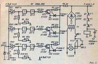
On chip D1 three channels of a temperature regulator are collected, providing temperature maintenance in three hives. Consider the operation of one of the channels. Element D1.1 performs the functions of a comparator with a trigger threshold of about 0.5U pit, D1.2 is a buffer element that provides
In the initial state (at a temperature higher than the threshold), the resistance of the thermistor RK1 is small and at the input of the element D1.1 the voltage is above the switching threshold. At the same time, its output is a low level, and at the output of D1.2 – a high level of voltage. The open transistor VT1 shunts the control transistor VS1. Therefore, the trinistor is closed and the heater is turned off.
As the temperature decreases, the resistance of the thermistor increases. When the selected temperature is reached, D1.1 switches. A high voltage level switches the element D1.2, and that, in turn, closes the transistor VT1. Current flowing through the resistor
R5, will open the transistor VS1 and the heater will turn on.
As the temperature in the hive increases, the resistance of the resistor will decrease and at some point the heater will turn off.
Resistor R6 with a stabilitron VD1 and capacitor C1 form a voltage regulator. The rectifier on the diodes VD “2-VD5 is common for all three channels and basically determines the power switched by the thermostat. With the types of diodes and transistor specified in the scheme, it is not less than 100 W per channel. The accuracy of maintaining the temperature when using KMT series thermistors, about ± 1 њ C. The whole scheme, including heaters, is powered from the 220 V alternating current network through a step-down transformer with a voltage on the secondary winding of about 42 V. The need for galvanic isolation from the mains and undervoltage is dictated Required for safety.
In the event of a failure of the thermostat, it is impermissible to permanently switch on the heater, leading to an increase in the temperature in the hive to dangerous limits. To prevent overheating of the hive, the system is equipped with a circuit of threshold thermal protection consisting of contact sensors Q1-Q3 (one per hive) and relay K1. The sensors are attached directly to the heater. If any of the thermoregulator channels fails, the temperature of one of the heaters rises rapidly. At the same time, the air in the hive does not have time to get much warmer. When the surface of the heater reaches a temperature of 70 њ C, one of the sensors triggers, opening the relay supply circuit, and it, in turn, de-energizes the entire system and provides an emergency light signal.
A short-term power cut-off does not cause the death of bees, because due to the high heat capacity and low thermal conductivity of honeycombs and honey, the temperature in the hive after the shutdown is kept for some time sufficient to redistribute the bees in the club.
When using resistors RK1-RKZ with a different resistance, it is necessary to change the values of resistors R2, R1 (and corresponding resistors in other channels). The sum of the resistances of R1 and R2 with the average position of the trimmer should be approximately equal to the resistance of the thermistor at operating temperature. Trimmer resistors are equipped with a simple scale.
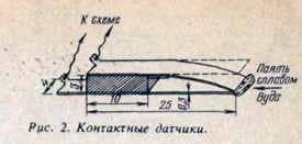
Contact temperature sensors are made of elastic bronze or brass plates (suitable contact plates from old relays) glued through a fiberglass laminate with BF-2 glue and (dried at a temperature of about 100 њ C.

Their geometric dimensions are not critical. Free ends of the plates are compressed and soldered with Wood alloy, and the sensor is fixed with a bolt or rivet on the metal part of the heater surface. The role of the heater is performed by two self-made thermoelements with a power of about 50 W each, connected in parallel and laid to the bottom of the hive through an asbestos gasket. The heater is connected to the regulator by an insulated wire with a cross section of about 1 MM2.
Resistors R1, R7 and R10-уръ-16, other нмф. Stabiliton D814B can be replaced by any of this series, tri-type KU201 with any letter. Before installing it, it is advisable to check the sensitivity of the trinistor to the opening signal. The transistor should open at a control current of not more than 4 mA. Diodes D242 with any letter index or any other, designed for a current of not less than 10 A, are placed on a ribbed radiator of 400 cm2 area through mica gaskets. The D1 chip is interchangeable with K561LH2.
Transformer T1 of industrial manufacturing type OCU-0.4UHL4.2 or any homemade having a secondary winding voltage of 30-40 V at a current of up to 10 A. Relay K1 type MKU-48 with a winding of 42 V. Switch SB1-PKE / 22-2U2.
All the details of the thermostat are mounted on a fiberglass board using the surface mounted method and, together with the transformer, are placed in a metal box placed in the immediate vicinity of the hives.
Graduation of the thermostat is carried out by placing a thermistor in a vessel with water installed on an electric stove. The temperature of the water is controlled by a mercury thermometer.
To control the switching of the transistor, instead of a heater, a table lamp can be connected, for example. Rotating the resistor R1 (respectively R7 or R10), the switching of the thermostat is achieved and a corresponding temperature value is plotted on the scale. After the calibration, the thermal sensors RK1-RK3 are connected to the electronic unit by a shielded wire of MGTFE and placed in a hive at the level of the lower bars of the frames.
If the artificial heating system is designed for servicing more than three hives, it is possible to produce additional channels for the thermostat according to similar schemes. In this case, it is advisable to feed them from a common transformer whose power is selected at the rate of 100 W per one beehive. Diodes VD2-VD5, also common for the whole system, must withstand current at a rate of 3 A per hive and be structurally placed with the transformer. Blocks of temperature controllers are more convenient to place near the hives, placing them in separate boxes and connecting a rectifier with a wire of about 1 mm2.
How to make a thermostat for heating beehives
