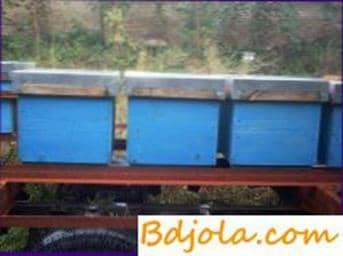
The transition of beekeeping and beekeeping complexes to intensive technology for the care of bees provides, in particular, the use of multi-hull beehives, multiple transport of apiaries for pollination and honey collection. At the same time, the mechanization of loading and unloading works becomes an integral part of the complex mechanization of the apiary. However, the shortage of serially produced cranes and forklifts in the farms disrupts the transportation plans, leads to the attraction of additional workers, often it delays the export of bees to the honey-combs, which leads to significant crop losses of many crops and shortage of honey. The absence of special means of small-scale mechanization is one of the reasons restraining the widespread introduction of multi-hull beehives.
In recent years, beekeepers have been increasingly using mobile platforms, but with rare exceptions they are not equipped with mechanization means, which complicates work, reduces labor productivity.
The simplest means of small-scale mechanization, the production of which is available to any household, enable the beekeeper to load the hive onto the platform without any help, quickly and easily inspect the bees, swap places and take away the honey-filled hulls with multi-body contents, etc.
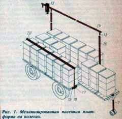
Sliding platforms can be manufactured on the basis of a two-axle tractor trailer type 2-PTS-4 or similar type of automobile type злч-817.
When converting this trailer, remove the beads, to the wooden floor of the platform bolts attach two guides from the corner 45X45 mm.
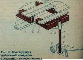 They are put on two bent P-shaped half-frames from the same corner and cover the boards 3.
To the semimrames 2 are welded along the length of the pipe 4 for fixing the supports 7 with a series of through holes 8. These holes allow you to adjust the height of the drawers formed by the half-frames 2 and the boards 3 and fix them with the pins through the hole 5. To reduce friction when extending the areas on opposite sides supports their ends put on two rollers. The supports 7 also have a groove 9 under the axis of the detachable wheels 6, the position of which is fixed by the pin through the hole 10, and the opening 11 for the lever 12.
The platform is equipped with common beehives. To do this, brackets 18 with holes 17 are attached to it. Scrapers 20 are made from corners 32X X32 mm with holes, metal bars 19 with a diameter of 12 mm with threads at both ends and nuts with washers. There is also a lifting device consisting of two lowered struts 16 (tubes of 34 mm in diameter), crossbeams 14 (pipes of 42 mm in diameter) with three pins 15 welded to it, a movable roller 13 with a cargo hook, a pulley block and a hive catch.
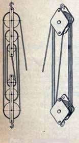
Fig. 3. The pulley blocks.
The gripper is a bent or welded U-shaped pipe 7 (diameter 27 mm), at the ends of which are installed at an angle of 45 њ in the holes of the axis 4 (diameter 10-12 mm) with squares and threads for attaching levers 5 and clamps 3 (strip thickness not less than 4 mm).
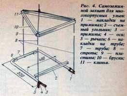
Two rubber pads 1 are attached to the clamps 3, and two 6 – to the pipe 7. Lanyards 8 are tied to the ends of the levers and to the pipe. The width of the sling is regulated by wooden blocks 10, connected together by wooden wedges 11 and metal plates 9. To expand the technological capabilities, the gripper is equipped with a removable square 2.
Before loading the hives onto the platform, one of the posts 16 is inserted into the bracket 18 and slammed into the ground. On the opposite side, the second rack is hammered into the ground and fixed by side extensions. In the posts insert the pins 15 of the crossbar 14, along which the roller with the cargo hook moves. The distance between the posts depends on the distance between the pins 15.
From the capture, remove the axles with levers and clamps, and the slings are fixed from the outside directly behind the ends of the pipe. A hive with a self-loader lifts the hive, drives it under the crossbar between the outrigger and the platform, the catch pipe 7 is brought under the bottom of the hive and with the help of a pulley lift the hive above the level of the platform. When lifting the bottom of the hive will reliably rely on the tube 7 of the grip and its square 2. Then roll the roller over the crossbar and lower the hive to its assigned place on the platform.
If necessary, between the platform and the crossbar, put an intermediate additional rack and load each row of hives to this rack first on one side, and then on the other. The hives on the platform are fastened with fasteners: the corners 20 are placed on the roofs of the hives, the rods 19 are inserted into the holes on the platform and corners and tightened with nuts.
Upon arrival, the trailer drawbar is removed and the platforms are pulled out. To do this, a support 7 is inserted from the top of the pipe 4 and fixed with a pin 5. A lever 12 is inserted into the hole 11, which has an end at the end of the boss, which prevents it from slipping out of the support hole.
The lever is lifted by the support along with the sliding platform and the wheels are put 6, fixing them with a pin. Then the platform with the hives standing on it is pushed to the stop in the stop (it is not shown in the figures) with the help of a chain block linked to a motor vehicle. Pulling out the pad, remove the pin from the hole 10, lever 12 lift the support, roll out from under it wheels 6 and put the support on the ground on the lining.
When inspecting the bees, the struts 16 are inserted into the brackets 18 and slammed into the ground. They are strengthened by crossbeams 14 with a movable roller and a cargo hook and a chain tackle with a grip. Before lifting the bodies, the axles, levers and clamps are placed on the gripper and the length of the lines is adjusted by the plates 9. The grip is turned on manually, lifting it up.
Пчелы если нет матки. Пчелы которые не жалят.
Pasechnye buildings